This is default featured slide 1 title

Go to Blogger edit html and find these sentences.Now replace these sentences with your own descriptions.

This is default featured slide 2 title

Go to Blogger edit html and find these sentences.Now replace these sentences with your own descriptions.

This is default featured slide 3 title

Go to Blogger edit html and find these sentences.Now replace these sentences with your own descriptions.

This is default featured slide 4 title

Go to Blogger edit html and find these sentences.Now replace these sentences with your own descriptions.

This is default featured slide 5 title

Go to Blogger edit html and find these sentences.Now replace these sentences with your own descriptions.

Thursday, February 18, 2016

Symmetric Power Supply 12V


Symmetric Power Supply 12V


1- Shematic :


12V power supply,Symmetric,Shematic,circuit componenets


2- Circuit Components :

1 Transformer: 230 V Primary / 9V-12V Secondary / 2A (A transformer steps down the mainvoltage)
4  Diodes (1N4001 to 1N4007) used as a bridge rectifier (1A bridge)
2 Filter Capacitors 2200uF/ 25V ( used for filtering of undesirable frequencies )
.  2 Filter Capacitors 100uF/25V
.  2  lED ( green and red)
1 Votage Regulator LM7812 ( we use it to produce a steady 12Volt DC ) 
1 Votage Regulator LM7912 
Share:

5 Volts Power Supply


                                           5volt Power Supply


1- Shematic: 


5volt,power supply,shematic,components


2- Components used in the diagram:


.  1 Transformer: 230 V Primary / 6V-9V Secondary / 2A (A transformer steps down the main voltage)
4  Diodes (1N4001 to 1N4007) used as a bridge rectifier (1A bridge)
. 1 Filter Capacitor 2200uF/25V ( used for filtering of undesirable frequencies )
. 1 Ceramic Capacitor 100 nF
.  1 Filter Capacitor 10uF/25V
. 1 Votage Regulator LM7805 ( we use it to produce a steady 5Volt DC ) 
Share:

Wednesday, February 17, 2016

The Electrical Voltage


                       Electrical Voltage


     The voltage corresponds to a potential difference between two points
a different circuit. The unity of the (pd) is the VOLT (V), symbolized by the letter U.
To measure this , you should use a voltmeter v. This one is always parallel branch
on the circuit.
     It is also called electromotive force (emf) and thanks to its action that the electrical current may exist.

    The greater the voltage, the greater the flow of electrical current (that is, the quantity of charge carriers that pass a fixed point per unit of time) through a conducting or semiconducting medium for a given resistance to the flow. Voltage is symbolized by an uppercase italic letter V or E. The standard unit is the volt, symbolized by a non-italic uppercase letter V. One volt will drive one coulomb (6.24 x 10¹⁸) charge carriers, such as electrons, through a resistance of one ohm in one second.

   A voltage produces an electrostatic field, even if no charge carriers move (that is, no currentflows). As the voltage increases between two points separated by a specific distance, the electrostatic field becomes more intense. As the separation increases between two points having a given voltage with respect to each other, the electrostatic flux density diminishes in the region between them.

1) voltage Notion:


  a- Terminal voltage of a battery:

   The negative terminal of a battery has an excess of electrons and these electrons are in default at the positive terminal. The size represents the charge concentration is called "electrical potential".
Between the two terminals P and N of the stack there exists a "potential difference" (noted VP-VN) or "voltage" (rated UPN)

   It is because of this potential difference that the battery is capable of moving free electrons, it is called "electromotive force" of the stack.

   Note: The elevation of a place can be defined only in relation to an altitude marker (sea level, level of an aerodrome ...)

Similarly, the potential at a point can be defined only by its difference with a reference potential ("ground" of the circuit, the negative potential ...)


b-Tension between two points of a circuit:


    For a given closed loop, over the electromotive force (emf) of the cell, the greater the current flowing in the circuit is intense.
The electron concentration varies throughout the circuit. This is the negative that it is the strongest and the positive it is the lowest.

   The potential V is the maximum and minimum positive to the negative terminal.


Between points A and B of a circuit can be defined as a potential difference (VA-VB) or voltage (UAB).


2) Measurement of the voltage:


 a- Unit of voltage:


  The unit of voltage is the volt (in tribute to Alessandro Volta)
  The symbol of the volt is V.

  Measuring a voltage:


  For measuring a voltage we use a voltmeter.


voltage,tension,unit,voltmeter

                                                                    The voltmeter symbol is:


b-Use of a voltmeter:

   To measure the voltage between two points A and B of a circuit, connecting a voltmeter in parallel between these two points.

   The terminal marked V must be connected to point A and the terminal marked COM to point B. It then measures the voltage UAB
If we ignore the magnitude of the voltage to be measured, it is prudent to place the voltmeter to its highest caliber when connecting.

   It must then reduce this caliber, if necessary, for better display: The right size is the smallest size immediately above measure.


voltage,tension,unit,voltmetervoltage,tension,unit,voltmeter


3) Voltage in circuits:


 a- Terminal voltage of a single dipole:

  If the voltage across an isolated dipole is not zero, the dipole is a generator.

Note: A voltage can exist in the absence of any electric current.


b-Voltage between the terminals of a dipole, traversed         by a current:

  If a dipole is traversed by a current, a voltage between its terminals exist.
Note: A current can not flow in the absence of tension.

.Case of a connecting wire:

   The voltage between the two ends of a good bonding wire is negligible.

Note: The wire should not be too long nor too short. Its electrical resistance should be negligible compared to the resistance of the rest of the circuit.

.Case of a switch:

   The voltage across a closed switch is negligible as the voltage across a wire.

The voltage across an open switch is equal to the voltage at the generator terminals (single circuit) or to the voltage across the branch in which it is placed.


Consequence: When a receiver is connected to a generator by good wire connection, the voltage at the receiver terminals is equal to the voltage of the generator since there is no "voltage drop" in connection wires.


voltage,switch,wire


c-Additivity law tensions in a series circuit:


   The voltage across a set of dipoles in series is equal to the sum of the voltages across each of them.

In the example below c:
P and A are the same potential
B and C are at the same potential
D and N are the same potential
additivity,law,tension,circuit
                                             UPN = UAD = UAB + UCD


d-Law of equal tensions in a bypass circuit:


   Two dipoles connected in shunt to the terminals of a generator are subject to the same voltage of that generator.

In the example below :
P, E, A and C are at the same potential
N, F, B and D are at the same potential


                                      law,equal,tensions,circuit
                                            UPN = UEF = UAB = UCD


Generalization:

We can take any three points A, B, C of a circuit in which the potentials are respectively VA, VB, VC.
UAB + UBC = (VA - VB) + (VB -VC)
UAB + UBC = VA - VB + VB - VC = VA - VC
UAB + UBC = UAC


4) Short circuit:

    A short circuit occurs when two wires having different potentials come into contact.
The dipole whose terminals are connected by a conductor is shorted.
A short-circuited dipole ceases to operate because the voltage at its terminals becomes negligible and the current flowing through it is negligible.

    The intensity increases in the circuit because the electrical resistance of the short circuit is much lower than that of the short-circuited dipole.
When a generator is short-circuited, the output current can be very important because it is constrained by the internal resistance of the generator and the resistance of the wire (very low). This current can destroy the generator or strongly warm the wire until a fire.


Note:  A battery has a lower internal resistance than that of a battery. A short circuit destroys in a short time, whereas a battery can withstand a short circuit for a few seconds.

Share:

The electrical current

Nature of the electrical current:

    To understand what is the electrical current, it must first begin with some physics and chemistry concepts.
Indeed, we must first look at the operation of an atom.
In particular the electrons circulating goshawks.

   In a metal conductor, all electrons are not used for connection of the crystal: have free electrons, it is their combined movement which ensures the passage of the current.

Electric current is an overall movement of electrical charge carriers.

                                                         charge of an electron: -1,6x10⁻¹⁹ Coulombs  
atom,electron

Direction of current:


    The conventional direction of the current is oriented in the direction of movement of positive charge carriers. They come out of the positive terminal and enter the negative terminal of the generator.  

current,charges   

direction,current


 Intensity :                       


  Briefly, a "time of change" At, an N number of charges carrying a quantity of electricity (Q). • Q So the amount of variation will be equal to N * Q. There will appearance of an electric current.

the intensity (I) is defined by: I = • Q / .DELTA.t
I is given in amperes.
• Q coulomb.


.delta.t Second.  

      
Measuring :


    We measure, the intensity of an electric current with an ammeter that plugs in series with the dipole that is to be measured.
ammeter,measure,dipole,intensity


The electrical circuit:

 To achieve an electrical circuit must be at least:

a generator
a receiver
Drivers liaison son
An electric current can be established in a CLOSED system!
A branch is a circuit portion between nodes.


Law of nodes :


  In the universe nothing is created, nothing is lost, everything is transformed!

The node law reflects this principle with the conservation of the quantity of electricity.

current at the start is the same in the end, to be more precise

The sum of the currents arriving at a node is equal to the sum of the currents that leave the node.


 Diagram of different electrical nodes:  


schéma d'un noeud électrique


law,nodes,current

law,nodes,current
                 
Share:

Tuesday, February 16, 2016

Resistor color coding


Resistance Color Coding:


1- What is a resistor ??

   A resistor is an electrical component that limits or regulates the flow of electrical current in an electronic circuit. Resistors can also be used to provide a specific voltage for an active device such as a transistor.
   All other factors being equal, in a direct-current (DC) circuit, the current through a resistor is inversely proportional to its resistance, and directly proportional to the voltage across it. This is the well-known Ohm's law . In alternating-current (AC) circuits, this rule also applies as long as the resistor does not contain inductance or capacitance.
    Resistors can be fabricated in a variety of ways. The most common type in electronic devices and systems is the carbon-composition resistor. Fine granulated carbon (graphite) is mixed with clay and hardened. The resistance depends on the proportion of carbon to clay; the higher this ratio, the lower the resistance.
2- What is a color coding ??


     We can use “Color coding” in to identify between many different electronic components. usually for resistors, but also for capacitors, and others. 

3- How to Identify Resistor Color Code ??


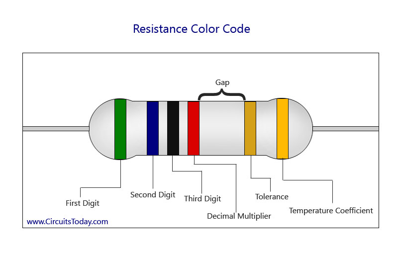
    The figure below shows the layout of the bands, the multiplier and the tolerance value of a 4.7K resistor. For a 4 band resistor, an additional temperature coefficient band is provided.

The gap between the multiplier and the tolerance specifies the left and right side of the resistor.  So here are the key points:
4 band resistor – has 3 color bands on left side and one color band on right side. First two bands represent significant digits, the 3rd band represents multiplier and the fourth band on right side represents tolerance.
5 band resistor  – has 4 color bands on left side and one color band on right side. Here the first 3 color bands represent significant digits, fourth one represent multiplier and the 5th one on right side represents tolerance.
6 band resistor – has 4 color bands on left side and 2 color bands on right side. Here the first 3 color bands represents significant digits, fourth one represents multiplier, 5th one represents tolerance and the 6th one represents temperature coefficient of the resistor.

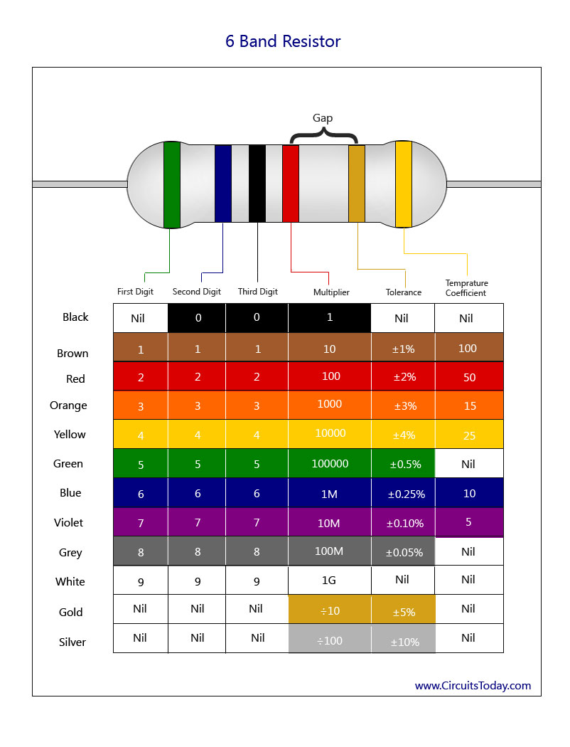
4- Resistor Color Code Chart:

    I have presented 3 charts below ; which are exactly resistor color code charts for 4 band, 5 band and 6 band resistors respectively.

Band 1 – First digit value of resistor
Band 2 – Second digit value of resistor
Band 3 – Third digit value of resistor
Band 4 – Decimal Multiplier
Band 5 – Tolerance Value
Band 6 – Temperature Coefficient
      I hope that everything is clair !!
Share:

Pages

Blogroll

Powered by Blogger.

Find Us On Facebook

Random Posts

Flickr

Social Share

Events

Recent comments

Recent Comments

Popular Posts

Most Popular

Blogger templates